Controlling how flag notes are attached to leaders (part 2)

This entry is part 2 of 2 in the series Controlling how flag notes are attached to leaders

I’m finally getting around to part 2 of my article Controlling how flag notes are attached to leaders.  Sorry for the long delay.  There’s been a lot going on IRL.  Also, for a very brief .001 second, I thought it might be funny to just do a bunch of part 1’s and never get around to doing part 2’s or 3’s.  Unfortunately, that would only be funny to me, so it wouldn’t really be funny at all. 

Add flag notes to drawings using annotation borders

In addition to flag note symbols mentioned in part 1 of this article, another way to create flag notes is with the use of annotation borders.  Depending on the results you want, there’s two ways to add borders.  The method is the same, but selection choices make for slightly different results.

1. Create an annotation note with a leader.

2. Type in the number of the flag note.

3. While still editing the annotation, highlight the number (either using SHIFT and LEFT ARROW or by selecting with the mouse)

4. While remaining in the edit mode (with the text highlighted), click on the Border drop down box in the PropertyManager.  Choose the required shape.


5. Choose OK and this will be your result.  Note the gap between the leader shoulder and the flag note (image below).  This is similar to the result when using a flag note symbol from the Symbol Library.  For triangles, this border method produces an equilateral triangle, where the Symbol Library is an isosceles triangle.

Flag note with touching leader (no gap)

Some people may prefer a flag note that touches the shoulder of the leader.  This is my personal preference too.  It follows the same look and feel as balloons and other symbols.  To achieve this style, follow steps 1 and 2 above, then continue with these steps below.

3. Exit the edit mode.  You should see a leader with just a number.

4. Select the leader note as one entity (LMB click anywhere on the leader note; shoulder, arrow, text, doesn’t matter).

5.  With the note selected, click on the Border drop down box in the PropertyManager.  Choose the required shape.


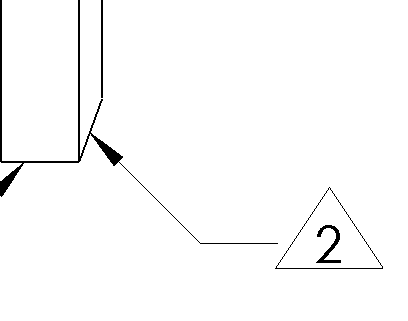
6. Choose OK and this will be your result.  Note the leader shoulder connects with the flag note (no gap).

I hope this How-to (or is this a Tips and Tricks?) helps!

Controlling how flag notes are attached to leaders (part 1)

This entry is part 1 of 2 in the series Controlling how flag notes are attached to leaders

SolidWorks provides the ability to support many different shapes for flag notes.  In addition to shapes, there are several methods in SolidWorks to create flag notes on a drawing.  Each method gives a slightly different result in how the flag note symbol looks and how it is attached to the leader line.  Part 1 of this article will cover shapes and the flag note symbols.

Flag note symbol shapes

There are two general methods to add flag note symbols to an Annotation Note.

The first (and older) method is to use the symbol library.  There are literally hundreds of symbols included within the library.  The library supports triangle, square and circle symbols for numbers and letters, with or without the period.  This method inserts a tag into the Annotation Note, which then generates the flag note symbol, based on existing data in the gtol.sym file.

Using the Flag note symbols from the symbol library

To use this method, create the Annotation Note with a leader.

While in the edit mode, click on the Add Symbol button in the PropertyManager.

This opens up the Symbol Library.  Pick the appropriate flag note symbol and OK.This opens up the Symbol Library. Pick the appropriate flag note symbol and OK.

This will insert the symbol into the Annotation Note.

If the triangle is chosen, the resultant symbol is not an equilateral triangle. The square and circle symbols are truly squares and circles, respectively.  Note the gap between the flag note and leader.  This gap can get bigger or be completely removed with a different method, which I will go into in part 2 of this article.

Trying to move an annotation arrow but drawing view moves instead?

Lock View Position - Shortcut menu

Have you ever tried to move an arrow of an annotation note, but instead the drawing view itself moved?   To fix the mistake, you are forced to undo and retry again.  The problem can pop up fairly frequently when trying to move balloons on an assembly drawing.  If a balloon is pointing to a vertex of the model, it is very difficult to select the arrow instead of the vertex point.  This can be very annoying.

So, how does one gain control over these wily drawing views?  SolidWorks allows users to lock the view’s position on the drawing.  Locking the view will prevent it from accidentally shifting when trying to move the annotation arrow.  To lock a view’s position, RMB click on that view.  This will open the Shortcut Menu.  Select Lock View Position.  This setting will lock the view’s position.  Of course, you can undo this by returning to the Shortcut Menu and selecting Unlock View Position.

.

————–

Update for SOLIDWORKS 2014: You no longer have to lock view focus or filter selection.  In SOLIDWORKS 2014, you can now simply select the balloon first, then select the tip of its arrow.  This will allow you to move the arrow (reattach it somewhere else) without any workarounds.

SolidWorks Assembly: Virtual Component Not Found?

Original article written by Nick Beattie, republished with permission of Symmetry Solutions.  Image added by Matthew Lorono. 

Having problems opening legacy assemblies that had parts saved internally? If you’re getting the “Unable to locate the file…” error referencing a temporary folder, your problem might be in the naming!

In SolidWorks 2009 and prior, you could rename the entire extension of the virtual component saved within the assembly.  For example a virtual part named “[vpart1^assembly1]” could be renamed to “[Vpart^Assy]” or simply “[vpart].” It was also possible that while doing a Pack and Go, the assembly would be renamed, but not the virtual component. Starting in 2010, this was changed so that only the “part” portion of the name could be changed. A virtual component named “[vpart1^assembly1]” can only have the “vpart1” portion renamed, while the “^assembly1” will always be the same as the assembly it is stored in.

If the legacy file you’re trying to open in SolidWorks 2010 or newer has had the assembly portion of the component renamed, it will not recognize it as a virtual component and will try to find the file. To get the file to open properly in 2010 and later, you will have to go back and open the part in 2009 and find the virtual part. Any parts shown with brackets such as [vpart] will need to be renamed to have the full current assembly name after the carrot. If you assembly is named “assy123” the virtual component needs to be named “[vpart^assy123].” Save the assembly with the renamed component. Now your assembly should open properly and recognize the virtual component!

Hidden SolidWorks Commands – compiled by Scott Baugh

SolidWorks Help file is notoriously unhelpful at times.  It has evolved over the years to improve its usefulness.  However, there are still many under-documented functions within the Help file or commands that are completely undocumented.  One day in January 2011, Scott Baugh asked a sincere and innocent question in the SolidWorks area on Eng-Tips.

Does anyone no (sic) where I can find a document with hidden SW commands. There are some key strokes and commands in SW that are not always listed in the help, or if they are they are overlooked very easy (sic).

From there, a long thread of comments grew.  Someone mentioned that users can print out a list of keystroke assignments.  This isn’t what Baugh was looking for. 

Then, the list of “hidden SolidWorks commands” began as people submitted commands they felt were obscure or impossible to find in the SolidWorks Help file.  It wasn’t long before Baugh offered to compile the list into a document.  At first, the idea was to build the list in a discrete document.  However, Deepak Gupta suggested GoogleDocs. 

From there, Baugh built the list of “hidden SolidWorks commands”.  There were three types of items added to the list:  commands that are truly undocumented, commands that are under-documented (full functionality isn’t described), and commands that were too hard to find within the documentation.

Baugh then brought the topic over to the SolidWorks Forums, where the discussion further exploded.  SolidWorks staff chimed in to address several points, but also to learn.  Jim Wilkinson provided several detailed responses to help bring clarity to the conversation.  Through his efforts, he also discovered several areas where improvement to the SolidWorks Help file is needed. 

The Hidden SolidWorks Commands list is now a treasure of numerous golden nuggets.  It’s not long, yet it can take awhile to fully explore.  Check it out.  If you have any further suggestions, feel free to leave a comment here, or in either the SolidWorks Forum thread or the Eng-Tips thread.

Hidden SolidWorks Commands