New in SolidWorks 2014 (not mentioned in the What’s New): View rotation angles everywhere (Part 3)

This entry is part 13 of 13 in the series New in SOLIDWORKS 2014

With all the new functionality with view labels in SolidWorks 2014, some ancillary enhancements have also come about as a result from customer feedback during Beta Testing.  One of these enhancements has been the new capability to display any view’s angle within an annotation note.  Why would anyone need something like this?

Well, there are four default options for the display of the angle symbol auxiliary views.

  • Show rotation symbol with rotation angle
  • Show rotation angle
  • Show the text “ROTATION” followed by the rotation angle and direction
  • Show just the angle

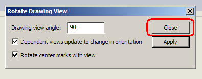
If your company chooses to display just the rotation angle (as is common for GOST drawings), it is still sometimes necessary to display the rotation angle.  Because the view label is a global setting within the drawing, there’s no way to accomodate this deviation from the standard settings without having some hugely complicated user interface to track individual labels here and there.  So, instead, one additional annotation tag has been added.  The advantage is that this new tag is available for any drawing view (not just auxiliary and section views).  The new tag is <VIEWANGLE>.  Type this into any annotation note.  As long as that note is a attached to a view, that view’s angle will be shown.  As an example, this new tag can be added to the auxiliary view label after the <VLANGLE> tag (or anywhere else in the note).

View rotation angle in any annotation note

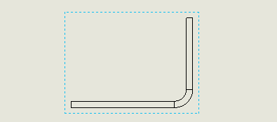
The settings and the result of using the new tag:

Adding the tag to add back the angle

New in SolidWorks 2014: View label overhaul (Part 1)

This entry is part 9 of 13 in the series New in SOLIDWORKS 2014

Drawing View LabelOn Drawings, view labels are special annotation notes that are attached to views such as Detail, Section and Auxiliary.   Previous versions of SolidWorks tightly controlled these labels via the Document  Properties (Tools>Options…>Document Properties tab>Views Labels).   When changes were made to view labels in the Document Properties, those changes were then forced onto all view labels of that type throughout the drawing.  Sometimes you might want to add specific information to a particular view.  SolidWorks often reverted manual edits to the view label.  The settings within the Document Properties were enforced to the exclusion of other edits.    There is a setting that allows you to override this behavior called “Manual view label” in the view label’s PropertyManager.  The drawback of this setting is that elements within the view label all become simple text and no longer update (e.g., if the scale of the view was changed, the view label would not automatically reflect the change).

Edit View Labels in SolidWorks 2014

SolidWorks 2014 introduces sweeping improvements to view labels.   First, a new setting is now available in the view label’s PropertyManager called “Use document layout”.  When this is checked, the Document Properties prevail.  When this is unchecked, you can manually edit the layout of the view label while still maintain the values for scale, view letter, name, etc.  This means, you can type your own text in-between or even on a separate row of text.

Look, I've added text!

Using tags for view label elements

The second improvement actually makes the first improvement possible.  View elements such as scale, view letter and name are now represented by tags.  These tags are viewable when editing the view label within the Edit Text Window.

Tags

Didn’t know that there was an “Edit Text Window”?  It’s always been there.  Right-click on any annotation note and choose “Edit Text in Window”.  This dialog has been expanded for view labels.

Edit Text in Window

As shown in the above image, buttons are now included that allow you to add view label elements.  The dialog is smart enough to know when elements are already included in the edit box or when the elements are not valid for a particular view.

You might notice that these buttons are also available when editing the view label directly in the graphics area too.

View label element buttons

Labelling views with angles (to be cont’d…)

In addition to all of the above enhancements, SolidWorks 2014 now has a tag that allows you to add a view’s angle of rotation.  However, more on that in a future article.  A lot more.

Visually determine the depth of a Broken-out Section in a Drawing View during preview

Adding a broken-out section to a drawing view is very useful to show detail inside of a part without resorting to creating an additional Section View.  The Broken-out Section tool in SolidWorks allows you to quickly add this detail to an existing drawing view by simply drawing a closed spline and establishing a depth.  A preview option allows you to see the result of your choices.  The drawing view updates in real time as you change depth.

However, sometimes, it is hard to visualize the depth while you are creating the broken-out section.  Some users will simply step through various depths until the broken-out section looks about right.  This trial and error method can be time consuming.

The Broken-Out Section tool is actually smarter than that!  It detects when there are projection views of the current view (either parent or child).  If there is a projection view, you can click on the specific feature you wish to slice with the broken-out section.  To use this cool function:

  1. With the Broken-Out Section tool active and cut area established, click on the Depth Reference field in the PropertyManager. 
  2. In the adjacent side view, you will see a yellow line that represents the current depth of the broken-out section cut.  Click on the feature you wish to cut through.  The depth line will shift to the center of that feature.
  3. Click OK to accept.

The above method may not always be feasible.  Perhaps the detailed components are too large to show the multiple views on screen at the same time.  Or, perhaps there is no feature that readily provides desireable results.

Here’s a trick that may help.  Use 3D Drawing View tool to rotate the view in 3D.  As you adjust the depth in the PropertyManager, the 3D view of the model will update accordingly.

1. With the target view highlighted, choose 3D Drawing View tool.

2. Rotate the view to a desirable angle.

3. In the PropertyManager, change the depth.

4. Select OK in the PropertyManager when desired depth is found.  Then exit the 3D Drawing View tool.

The result is a happy broken-out section in your target drawing view.

Rotating a Drawing View

Sometimes one need to show a rotated view in the drawing. If is available in the standard view, once can simply place it as desired. If there is no view as required, one may go to part or assembly and create a new view orientation and then use that in the drawing. To avoid that one can simply rotate the drawing view as required.

1. Click on the view or select the view you want to rotate.

2. Click on Rotate View on the heads up tool bar or standard tool bar.

3. You’ll now see a Rotate Drawing View pop up window.

4. Fill in the desired angle value (I have used 90°). You can also key in a negative value.

5. Once you have keyed in the desired value, click on Apply and view will be rotated.

6. Then click on close to exit the command and you’ll have a rotated view.

Using Empty Views (Part 2: How to use them)

My articles on Empty Views in SolidWorks have been long in coming.  This is not due to the topic being complex or anything.  It’s just taken me that long to get around to this series.  (There’s been a lot of other stuff to talk about in the meantime, such as SolidWorks World 2009, something called a 3D mouse, and rants about this or that.) The Part 1 article in this series discussed how to make, place and size Empty Views.  Part 2 now discusses how to use them once they are created.

Use Empty Views as quick Zoom to selection locations

OK, let’s say that one empty view each represents the title block, revision block and drawing notes.  How does one quickly move about the drawing to view these areas?  There are several methods available in SolidWorks.  The following method is likely less common, but is perhaps quicker can more common methods.

First, assign a shortcut to Zoom to selection function.  Zoom to selection is found under View pulldown>Modify>Zoom to selection.

Zoom to selection location

To add the shortcut (for much quicker access to this function), goto Tools pulldown>Customize…>Keyboard tab> and then search for “zoom to selection”.  From there, simply add a keystroke as the shortcut for Zoom to selection and choose OK to save.

Now here is how to use this shortcut with Empty Views.  With the drawing open and with no views selected, look over in the FeatureManager.  Select any one of the Empty Views (or any view for that matter).

FeatureManager display of views

As this point, simply hit your shortcut keystroke for Zoom to selection.  The viewport will immediately zoom to the area identified by the Empty View.

Zoom to selection of empty view

Choose another view from the FeatureManager and hit your shortcut for Zoom to section again.  Each time, the viewport will immediately zoom to the area defined by the selected view.

Using Empty Views for PDF bookmarking

As an added bonus, any views created on the drawing (including Empty Views) will become bookmarks if you save that drawing as a PDF.  This adds greatly to the navigability of PDF files for everyone who uses them.  Within PDF Reader, the bookmarks will appear to the left (similar to the FeatureManager in SolidWorks).  Simply LMB click on the desired view, and PDF Reader will jump to that location.

There are some pitfalls with saving a drawing as PDF, so if your company is experiencing those, then it is not recommended that drawings be saved as PDF.  In those cases, print to PDF works better.  Unfortunately, bookmarks are not created when printing a drawing to PDF.

Conclusion

The one thing that frustrates me about SolidWorks Empty Views is that SolidWorks Corp reduced their functionality (as discussed in Part 2).  However, with a simple hack, they can be used as drawing bookmarks, to contain drawing notes,  and to add functionality to PDF files.  Additionally, they are always useful for containing sketches, as noted in Part 1 of this series.

Using Empty Views (Part 2: Creation)

In this article I’m going to cover how to create an Empty View, and the ugly hack for making it a desired size.  In Part 2, I will cover how to use Empty Views for quick zooming and bookmarks in PDFs.

Creating Empty Views

Creating Empty Views is easy.  With a drawing open, goto Insert pulldown>Drawing View>Empty.

Add empty view to drawing

SolidWorks will then ask for a location on the drawing for the Empty View. Simply LMB click at the desired location.  In the example below, I’ve placed the Empty View in what might seem to be an very unusual location (covering the Revision Block table).  I’ll cover why in Part 2 of this article.

Pick location on drawing

Ugly Hack

To get the Empty View to stretch across the full length of the Revision Block table, we’ll need to employ an ugly hack.  Within the new Empty View, draw a line that starts from the corner of the border. Terminate the other end at the vertex of the table at other end.  The endpoints of this line will not attach to these two vertices, but will drop on top of them when the line is created.

Pick location on drawing

The result is an Empty View sized as required. The way to hide the line in this hack is to place it directly over another line (in this case, the Drawing Border).  (A RMB click on the line and choosing the Hide function will not work.  The view will resize back to its default shape.)

Pick location on drawing

Now RMB click on the view and choose the Lock View option.  This will keep the view in place (preventing it from accidentally shifting around).

Making the Empty View useful

To make this new Empty View useful, rename it in the FeatureManager.Renaming the Empty ViewRenamed Empty View

This will allow for easier identification when it comes time to use this (and any other Empty Views).  Part 2 will explain more about this and the reason for these additional steps.